Multi-region high availability architecture diagram
Most cloud outages affect a single region. A multi-region design keeps a second copy of the system in another region so the service can keep running, or come back quickly, when the first one fails.
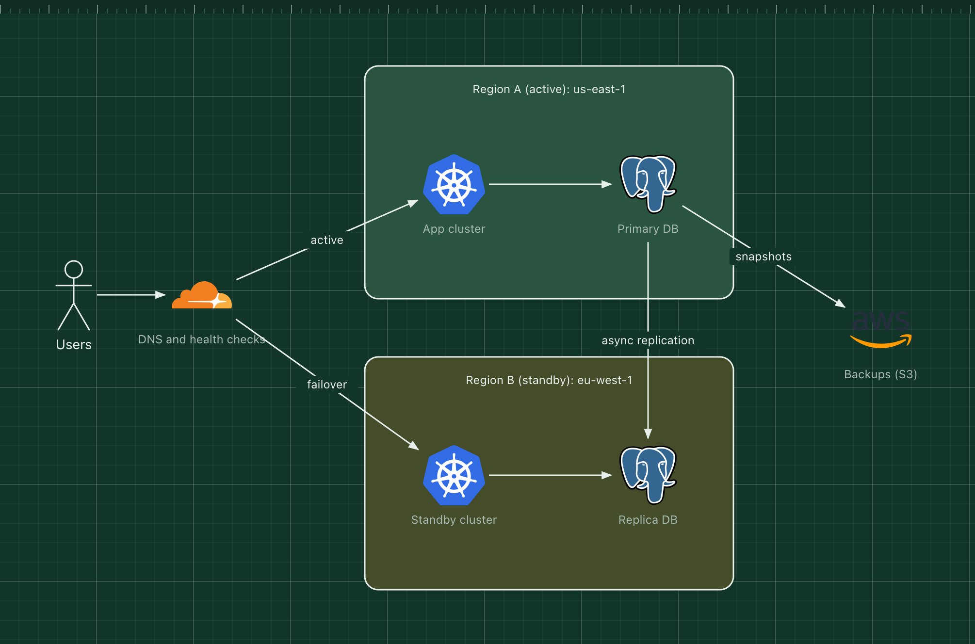
This template shows an active-passive setup, often called a warm standby: one region serves all traffic, while the second runs a scaled-down copy with a continuously replicated database.
What's in the diagram
- DNS and health checks
- Probes each region and points users at the healthy one. Short DNS time-to-live makes failover quicker.
- Region A: app cluster
- Serves all traffic in normal operation.
- Region A: primary database
- Accepts all writes and streams changes to the replica.
- Region B: standby cluster
- Runs the same deployments at minimum size, ready to scale up.
- Region B: replica database
- An asynchronous copy, promoted to primary during a failover.
- Backups (S3)
- Snapshots copied across regions, for recovery from data corruption that replication would copy too.
How a request flows through it
- In normal operation, DNS sends users to region A.
- Every write to the primary database is replicated to region B within seconds.
- If region A fails its health checks, DNS starts answering with region B's address.
- The replica is promoted to primary and the standby cluster scales up.
- When region A recovers, it is rebuilt as the new standby, and you can fail back during a quiet period.
When to use this architecture
Use it when an outage of a whole region would cost more than running a second region, and when a few seconds of lost writes are acceptable. If you need zero data loss or zero downtime, look at active-active designs, which are far more complex because both regions accept writes.
Ways to adapt the template
- Write down your recovery time and recovery point objectives, then size the standby to meet them.
- Rehearse the failover regularly; an untested standby is a hope, not a plan.
- Use a managed global database if your provider offers one.
- Add a third region for read traffic close to users.
How to customise this diagram
- Open your copy. Click Open in the editor. The template opens as your own project, saved in your browser. Nothing is uploaded.
- Rename the parts. Double-click any label, such as “DNS and health checks”, type your own name, then click outside it. Arrow labels work the same way.
- Swap a technology. Select DNS and health checks and press Delete. Search the icon palette for the technology you use, drag it onto the board, and reconnect it by dragging its arrow handle onto the next component.
- Add what is missing. Drag more icons or shapes onto the board. Shapes include databases, servers, users, queues, mail, alerts and scheduled jobs.
- Adjust the zones. Zones are rounded rectangles with a fill colour. Resize them to fit, pick another colour from the selection bar, and press [ to send a zone behind the components.
- Export or share. Save the diagram as a PNG with the camera button, download the project as JSON with Export, or copy a link with Share.